AN OVERVIEW OF TRANSMISSION SWITCHING AND SWITCHING METHODOLOGIES

Transmission systems are subordinate to overvoltage surges caused by the operation of transmission line switches. switching methodologies these over-voltages occur on the transmission network as traveling waves that occur in a microsecond period of time, usually the result of the deployment of circuit breakers. The intensity and shape of the switching overvoltages differ with the system and network setup parameters. With the same system variables and network configuration, the switching overvoltages are heavily dependent on circuit breaker operation dynamics and point-on-wave where the switching activity happens.
To optimize the economic efficiency of power deployment on a bulk electricity network, transmission lines are switched into and out of the network. The optimum problem of transmission switching can be conceived as a question of efficiency with quantitative variables reflecting the position of each line. Optimal transmission switching is a revolutionary method of power grid control that uses this feature of electricity networks.
Switching methodologies:
Methods of switching illustrate how quickly the switch begins manipulating an internal object. There are three categories of methods for switching; store-and-forward, fragment-free, and cut-through method. Let’s get a detailed understanding of each of these approaches.
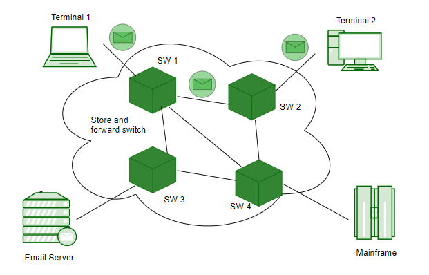
The store-and-forward switching method:
In this approach, the switch does not initiate the processing of the inner frame until it receives the entire frame. After the whole frame has been obtained, transfer validates whether or not the frame obtained is in good shape. If the frame you have got is in good condition, then only the switch can handle it. If the frame obtained is not in good condition, then the switch must delete it. The sender or source system executes the CRC (Cyclic Redundancy Check) algorithm on it after a frame has been developed. The number this algorithm produces is recognized as the CRC value. The CRC value is deposited inside the frame’s FCS field. The frame is the last data-packaging layer. The sender module loads that frame in the media after the CRC value has been stored. The store-and-forward system handles only those frames that are in good condition.
The cut-through switching method:
In this approach, the switch begins loading the frame as soon as it scans the frame’s MAC address for an endpoint. Ethernet frame stores MAC address location in the third field. Just after reading the destination address, the CAM table is checked and the frame forwarding begins premised on the match (although the frame may still enter the switch). This system does not test the state until forwarding a frame. This minimizes latency but also causes errors to propagate. It is the speediest switching process in all of the three switching methodologies.
The fragment-free switching method:
For this approach, the switch continues processing the frame after reading the frame’s first 64 bytes. The legal minimum capacity for an Ethernet frame is 64 Bytes. An Ethernet frame of fewer than 64 bytes is referred to as the Runt frame. A-frame with runt is a compromised box. This approach reduces the number of runt frames being turned on by Ethernet.
